F-drive e-bike conversion system
The idea to create a friction drive system has been born in my head a couple of years ago. I wanted to check how it is to ride an electric bike, but back then I did not have access to any. Upgrading my bike to be fully electric was not an option since I wanted to keep it as untouched as possible.
Then I found a friction drive solution and after some doubts about efficiency, I started to create my version of it. And here we are a couple of years later.. with an almost finished system.
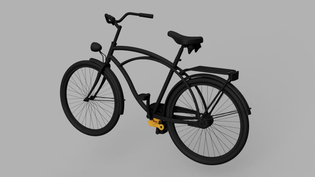
Table of Contents
How it works
The principle of a friction drive relies on pressing down roll to the tire to pass the drive. To simplify the system a little instead of a roller (which supposedly is powered by some tension belt) we can use a brushless outrunner motor where the rotator can act as a roller.
In this friction drive implementation to connect and hold the motor attached to the tire is used torque produced by the rotor. To make this solution works flawlessly a lot of tries and iterations were required (both in mounting arm design and software adjustments), but I am more than happy with the final result.
Comparing to traditional e-bike systems disadvantages of fdrive are obvious: less efficient use of energy, faster tire wear, and a problem with wet conditions. But before rejecting the idea advantages also need to be listed:
- little modification in bike
- fast and simple mount and dismount
- no motor resistance during normal biking (motor then is completely disconnected from the tire)
System overview
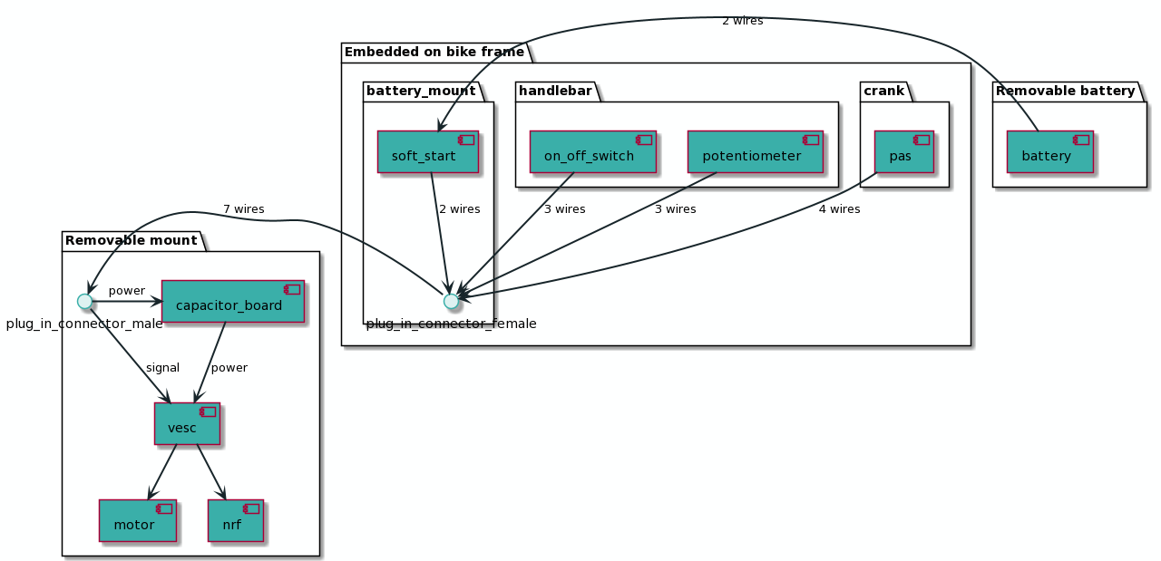
The system has been split into three sections. On consists of elements that have to be mounted on a bike frame, and two (battery, the motor with controller) that are easily removable. The goal was to enable an option when a couple of bikes can have Embedded part mounted on and the user can switch removable parts between them (I someone have i.e. road bicycle and cross bicycle and want to buy only one set).
Details and connection scheme can be seen on diagram:
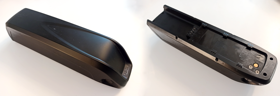
Battery
I have made a battery by connecting 50 individual 18650 cells in the 10S5P configuration. Each cell has a capacity of 2750mAh. So the total capacity of the battery will be:
Capacity = (3,7V * 2,75Ah) * 50 = 508,75 Wh
Taking into account that I live in Europe where the law allows to use max 250W and speed up to 25km/h that should give about 2h work on full throttle. Let’s say that efficiency is about 80% so the estimated range will be:
Range ~= ((508,75Wh / 250W) * 25km/h ) * 0,8 = 40,7km
But in practice range is much better due to fact that in Europe cyclist cannot use electric motor exclusively, it can only act as a support.
The battery got also a BMS system to balance the charger level of each section. The whole battery is packed into one of the universal battery cases.
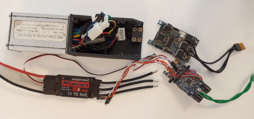
Controller
That part took a huge amount of time, I got information on some forums that generic BLDC controllers are ok, but I have never been happy with them. Some generate too much heat, some too much noise, others were lacking documentation to configure them properly. Chinese S06P was close to being the right one but I haven’t the possibility to modify the firmware for special friction drive and my pas sensor needs.
I also gave a try to ST motor controller evaluation boards but the SDK was too immature at that time. Then I saw on the shelf dusted VESC controller that I used for the e-skateboard project long ago and it fits my needs perfectly.
I have made a small table to compare controller candidates.
VESC is a powerful platform in terms of software compared to other solutions that you can find on the market. The configuration that you can do through dedicated PC and smartphone apps is quite extensive, but for me, the real power lies in the capability of writing your application on that platform.
| Controller | Prons | Cons | Price |
|---|---|---|---|
| Generic BLDC controller |
easy access, low price, cheap, small |
Too loud, Too much heat, closed source | ~15$ |
| STM32ESC1 | Open sourced, FOC possible, small |
poorly maintained SDK an PC tools | ~35$ |
| SC06 | rigid enclosure, nice cooperation with outrunner |
closed source, lack of proper documentation, big enclosure |
~30$ |
| VESC | Open sourced, big community, good PC tools, great FOC performance |
ready to go with rigid enclosure can be expensive | ~30$ |
Motor
The type of motor is already chosen by way of torque transfer - it needs to be an outrunner. At a time when the project started the most popular were brushless motors, so I picked a couple of them to try which suits best my needs.
After comparison, I chose BLDC motor 5065 270kV without hall sensors (to be precise is more kind of PMSM motor, but commonly they are called brushless or BLDC motors). It is powerful enough (1,5kW peak or close to this), has a good voltage constant (270kV for a diameter of 50mm is a sweet spot), is cheap (~30$) and as for now really reliable. It does not have hall sensors so not all controllers are gonna like him.
#ODOPICTURE MOTOR PICTURE
To make proper contact with the tire I have covered him with a piece of radiator hose. I found it in an agricultural shop and it turned out to be a perfect fit for the motor. Moreover, it reduces vibrations therefore drive is quieter (bike frame resonates pretty well). (I didn’t get that idea immediately, I made dozen of tries with skateboard grip tapes, sandpaper, inner tubes, but all of them fails after some time)
#TODOPICTURE MOTOR OUTER COVER
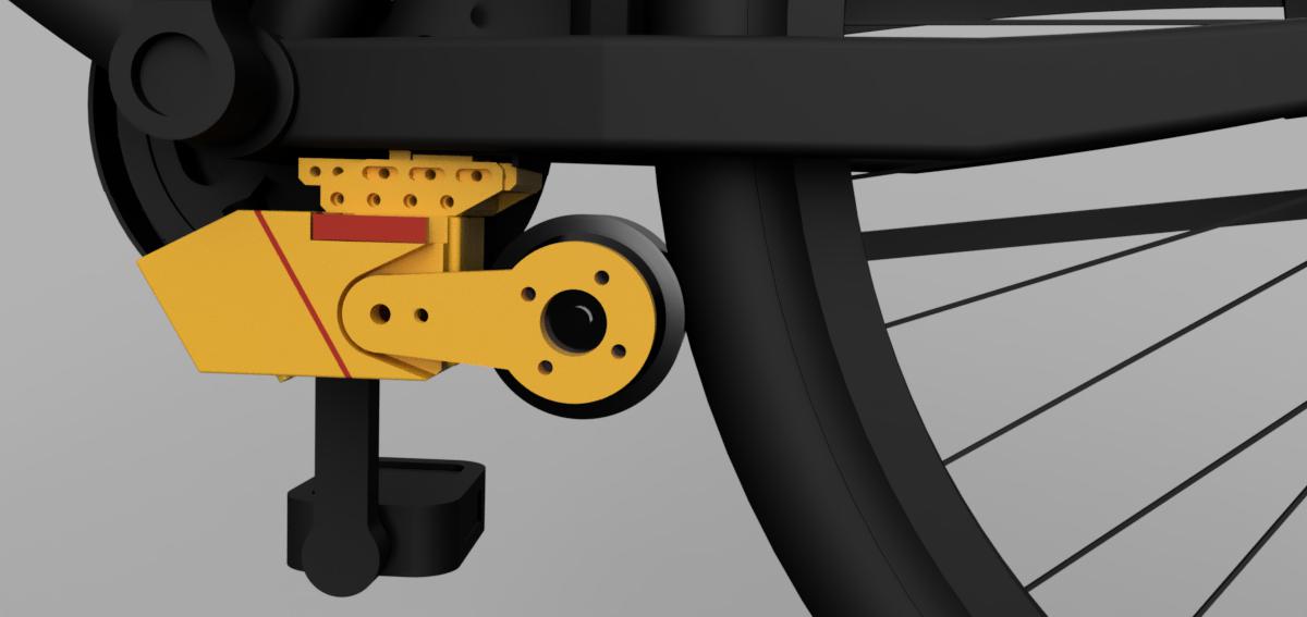
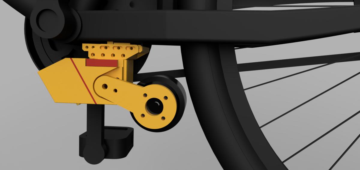
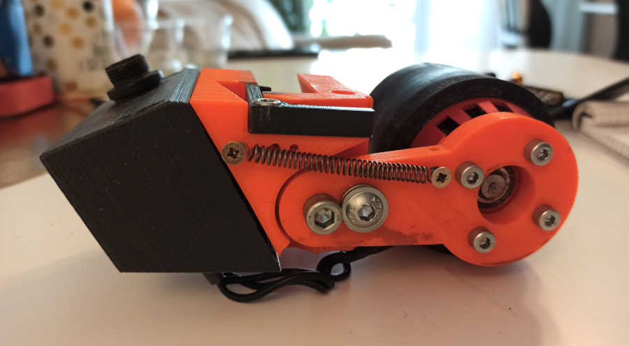
Mount
That’s the most difficult part for me since I never had an education in that field, at the same time it excited me the most. At first, I attempted with a steel sheet about 3mm thick, but the fulfillment of all mechanical dependencies and position adjustments was too hard.
At about the same time I bought 3D printed and installed Fusion 360 and that was it. Iteration after iteration the design was more clear (overall more than several dozen were created). The biggest challenge was to enable all position adjustments with plug-and-play possibility and still to be enough rigid to handle the drive transmission burden. The following pictures should explain how the mechanism works.
#TODOPICTURE MOUNT RENDER
Currently I am in a way to switch further to aluminum milled parts, but due to problems with access to the milling machine, it needs to be postponed.
Pedal Assist Sensor
Regular Pedal Assist Sensor gives information about one-way rotation (by regular I mean this 3-wire ~10$ ones). Some of them can provide information about reverse rotation but to a limited extent. Also, their fixing requires removing the crank which annoys me badly. So I decided to create my version of PAS.
Application (controller firmware)
Working with physical stuff on the software side is very cool. I have made another post about this application.
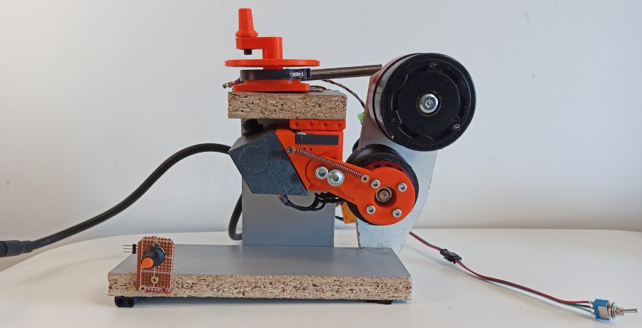
Test fixture
To efficiently work with software and electronics I have decided to create a simple test fixture, and that was it. Designing-Writing-Testing loop now was way faster, and the visible progress was motivating.
I took a picture of it, maybe it is not pretty but it is getting the job done.
Project future
The goal is to create two pieces of fdrive and use them daily and for short trips :)