VESC - cost-sensitive solution (~30$)
Playing with electronic speed controllers can be enjoyable and frustrating at the same time. I have always had a hard time using custom ESC’s when everything seems to work well and in the next second, some tangled wire or ESD charge kills an important chip or even one crucial I/O pin spoiling all the fun.
Most of the time I am working with a VESC controller thanks to the fact that it is open-source (in hardware and software) and very popular. Assembled, it costs around 70-100$ so burning it once or twice can discourage further work.
I was facing that problem for a long time, finally, it seems that I have found a way out and I want to share it with you. The idea is to assemble controllers on your own. The whole process includes ordering PCBs and parts (also a couple which is the most fault-prone) and assembling them by hand (it is easier than it seems). After that we can get 3 pieces of the controller with spare parts for the price of one assembled to go VESC. If you are interested, I invite you to read further.
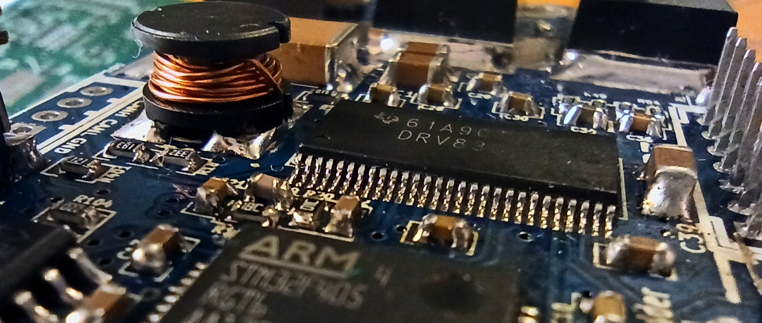
Table of Contents
- VESC - cost-sensitive solution (~30$)
- STEP 1 Gathering components:
- STEP 2 Assembly
- STEP 3 Programming
- CONCLUSION
STEP 1 Gathering components:
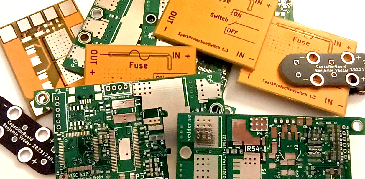
PCBS
Currently the best option to order them is to use JLCPCB manufacturer, (HERE is a comprehensive description of how to order boards). IMHO the basic set of pcbs for playing with VESC should contain at least:
- VESC main board (we will use version 4.12) (5pcs - 7$)
- VESC capacitor board (10pcs -2$)
-
AntiSparkSwitch (10pcs -2$)
- TOTAL: Boards 11$ + Shipping 5$: 16$
COMPONENTS
Bill of materials for VESC can be found on Benjamin Vedder github. Components needed for capacitor board and antispark switch need to be taken directly from the schematic. I am currently experimenting with replacing MOSFETs with cheaper alternatives with the same parameters and they work ok.
EXTRA
To play with VESC properly it is a good idea to order also:
- NRF52832 Bluetooth module, you can get one of these on eBay or Aliexpress. It allows connecting mobile apps to the device, controlling, checking the state of the device, making bridge connection to PC apps, and many many more.
PICTURE
- Potentiometer, Remote controller, or anything else that can be used as a control device.
- Programmer: some ST-link or J-Link (most ST development boards have ST-Link embedded into them)
STEP 2 Assembly
For many, this seems the toughest part, but it is not necessarily true. To assemble you need to have: Soldering iron, Soldering wire, Flux, Tweezers, Copper braid, Hot air gun, or a bit of thermal paste.
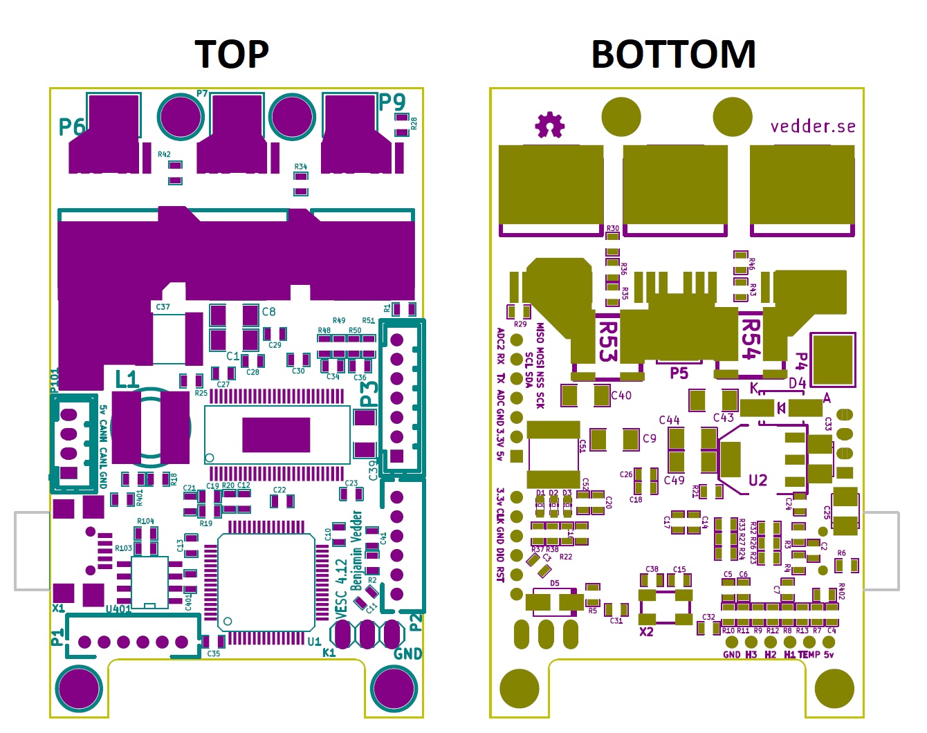
I have prepared top and bottom component placement prints for your convenience, you can print it and should easily assemble the whole board with it. Of course, you can also install Kicad software and look at the original schematic and the PCB design (also for AntiSparkSwitch).
If you do not have hot air to solder the thermal pad of the mosfet driver (DRV8302 - U3) you can smear it with thermal paste and solder only legs on sides, it should work sufficiently for most use cases.
STEP 3 Programming
Thanks to the courtesy of Benjamin we can download ready-to-go binaries with which we can flash our STM. Go to GIT repository and download the latest compiled version of VESC firmware (Precise link.
First of all, the bootloader needs to be flashed, a compiled version of it can be downloaded from HERE
The process of programming of STM32 processor is quite easy and can be found i.e HERE.
CONCLUSION
In that way, we got 3 VESC controllers and a bit of knowledge at a very competitive price. It is not a solution which suits everyone, but I found it the best and hope you are too. If you have any comments about this post or you would like to have something clarified more deeply please write below, or contact me directly.
#TODOPICTURE SOLDERED BOARDS