Fdrive application
Some time ago I have started creating an e-bike conversion kit, based on the friction drive principle. I found VESC to be suitable to act as a motor controller. The rest of the system is decribed in another post, check this out before going further in text. The component described here is connected with Pedal Assist Sensor, (it uses signals from this component).
Table of Contents
Architectural view
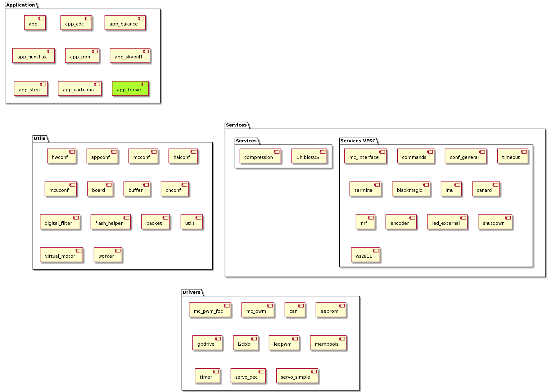
During my professional work, I found diagrams very concise communication path. Even though this project is developed only by me in my spare time, creating a couple of diagram speed up work and gives more joy of it. Placement of developed component in the VESC system has been made at the application level, which is highlighted in the next picture.
Cooperation with components
The most significant paths of cooperation are shown on the next diagram. I didn’t want to show all of them to not darken the diagram.
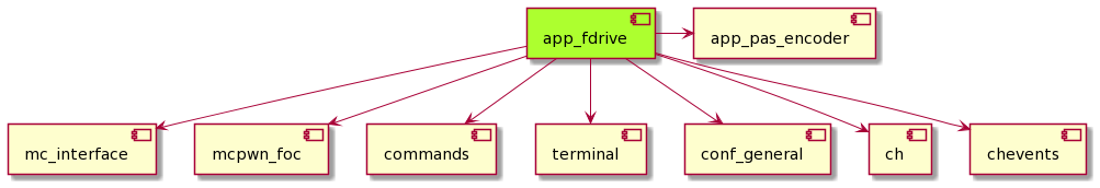
- app_pas_encoder - provides information about crank movement
- mcinterface - is used to control motor
- mcpwm_foc - also serves for motor control, but it is more low level
- commands - takes care about communication with user by command line
- terminal - used for registering callbacks from user input
- conf_general - gives access to flash emulated non-volatile memory
- ch - provides ChibiOS features
- chevents - also provides ChibiOS features but specifically in events scope
Main f-drive state machine
To handle the problem of attaching, miss-attachment, cooperation with a potentiometer, arming, disarming, and other functions proper state machine is needed. Below is my current variation on this problem
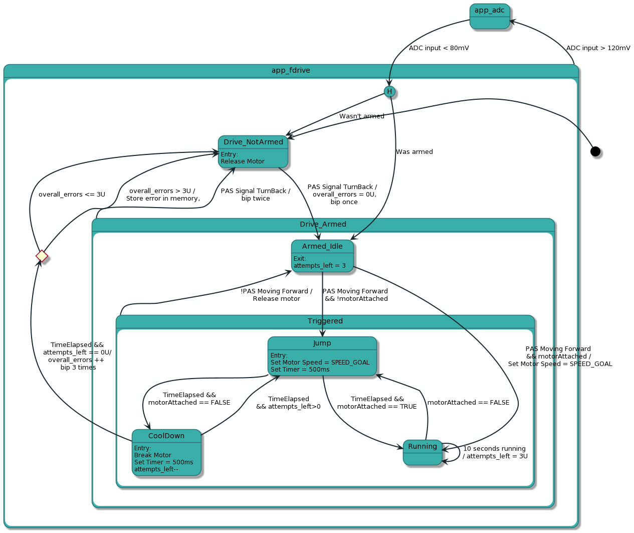
In general, the motor can be used exclusively by ADC (practically speaking handlebar throttle) or pedal assist sensor.
#define FDRIVE_APP_ADC_LOWER_THRESHOLD     0.080f
#define FDRIVE_APP_ADC_HIGHER_THRESHOLD    0.120f

switch(app_state)
{
    case FDRIVE_APP_ADC:
        ...

        if(adc < FDRIVE_APP_ADC_LOWER_THRESHOLD){
            app_state = FDRIVE_APP_PAS;
            break;
        }
        break;

    case FDRIVE_APP_PAS:
        ...

        if(adc > FDRIVE_APP_ADC_HIGHER_THRESHOLD){
            app_state = FDRIVE_APP_ADC;
        }
        break;

    default:
        break;
}
In ADC mode” steering is simple, the motor is driven in the way that throttle is tilted. Attaching the motor is the duty of the user.
Fdrive “mode” is a little more complicated: there are two main states Drive_Armed and Drive_NotArmed switched by PAS TurnBack Signal. According to that short sound signal “bip” (or twice “bip” for disarm) is generated by motor coils to give the user feedback about the system state.
Composite state Drive_Armed defines the strategy of attaching the motor to the tire, as not go to the details, only to say that app_pas_encoder component is continuously polled about crank rotation state and if it is forward it tries to keep motor attached. Code for this implementation id too long to be cited here, full source can be found on my Github..
Storage of configuration in non-volatile memory
If you look closely at the main state machine, you will see that there are a couple of parameters that are good candidates for calibration values (i.e. jump time, attempts limit). Having the possibility to change them without re-flashing the uC makes testing much easier.
Here VESC framework comes with help, within the conf_general module are embedded functions to store are read custom configuration.
/**
 * Read custom variable from emulated EEPROM.
...
 */
bool conf_general_read_eeprom_var_custom(eeprom_var *v, int address);

/**
 * Store hw-specific variable to emulated EEPROM.
 ...
 */
bool conf_general_store_eeprom_var_hw(eeprom_var *v, int address);
Our job is to prepare some meaningful struct with configuration, here is my attempt:
typedef struct
{
    uint32_t attach_time_ms;
    uint32_t cool_down_time_ms;
    float attach_speed_final_per;
    float attach_current_thr;
    uint32_t attempt_count_limit;
    uint32_t speed_goal_kmh;
} app_fdrive_config_type;

#define APP_FDRIVE_CONFIG_LENGTH sizeof(app_fdrive_config_type) / sizeof(eeprom_var)
//todo check if it is really helpful
typedef union
{
    app_fdrive_config_type config_struct;
    eeprom_var config_table[APP_FDRIVE_CONFIG_LENGTH];
} config_union;
I have also created a union to force the compiler to align struct in the same way, and I am using it to pass a struct to save/ read function. I am still not sure if it helps somehow, little //todo will track me back here later.
Closure
The application is not finished, I barely believe if it ever will be finished, there is always something that can be done differently. Fortunately, VESC can be updated through Bluetooth so I can make changes even in the assembled device.