Custom Pedal Assist Sensor (PAS) + VESC support
Pedal Assist Sensor (PAS) - is a device that can be mount on the crank of a bicycle which gives you information about the current movement of pedals. (On ebikes.ca you can find a broader description of these sensors.
Normally sensors have three wires and can track effectively the movement of the crank, although detection of the direction of the movement can be a little tricky. Therefore, since I have a 3D printer and I know a little about electronics I made my version of PAS.
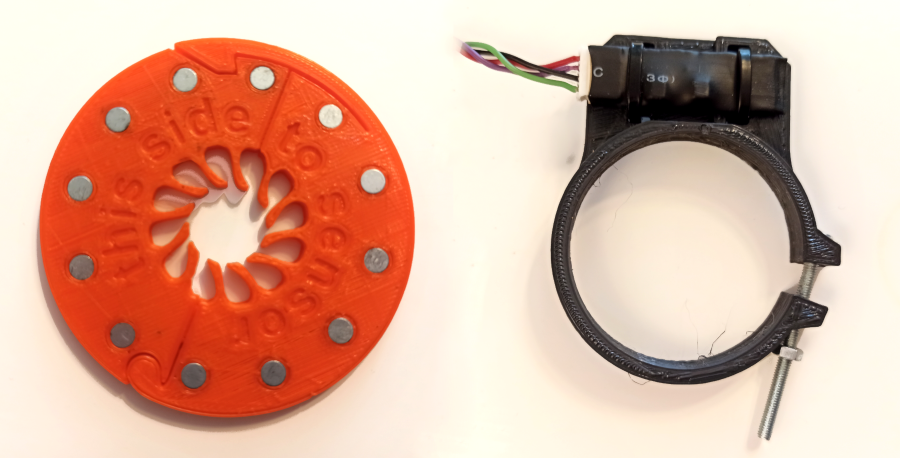
Table of Contents
Pedal Assist Sensor - market standard
I got a bunch of Varied width sensors that requires one wire to connect to uC. The signal that can be read looks like below:
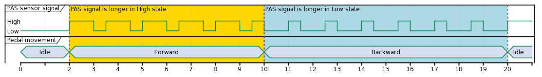
The distinction between forward and backward movement can be done based on Tu/Td ratio (ratio between time where the signal is on high and low level). Even when I am reading the previous sentence I see that measurement is going to be lame. And it is, I tried to improve it with some filtering, state detection, etc. but the results didn’t satisfy me at all. My attempt can be seen on GitHub repo.
Pedal Assist Sensor - my version
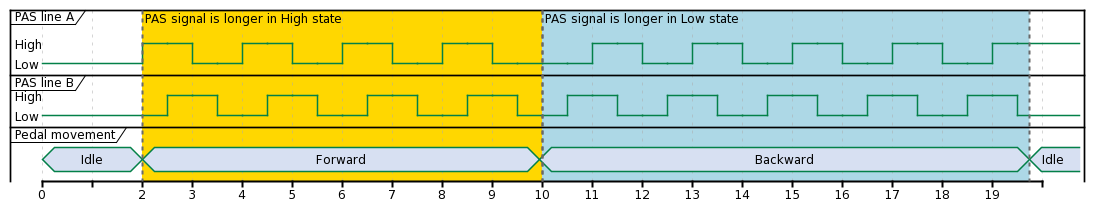
My fdrive application requires to have a proper distinction between forward and backward movement and also reliable information about full backward rotation. Knowing that I decided to implement sensing in an “encoder like” manner, that means at output I will get two signals (called A and B) crossing themselves differently according to direction, check the following picture for details.
Mechanical design
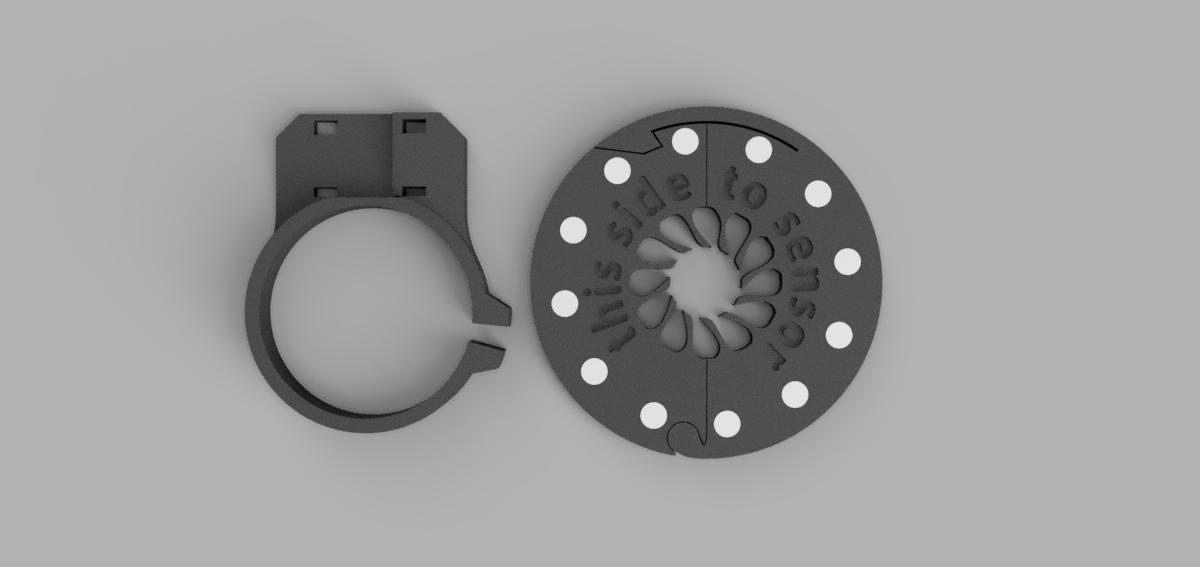
What I don’t like about the stock sensors is fact that you need to remove the crank to mount it on the bike. Avoiding that was the most crucial requirement. Earlier electronic tests when I checked signal quality gave me information that putting 12 magnets around the perimeter gives the best results. Knows all of that I turned on Fusion 360 and after a couple of iterations, I got something that is quite useful.
Electronic circuit
Earlier I thought that Hall sensors are simple, just buy a random one, connect the power supply and it’s ready. But I disregarded my opponent, there are many parameters (unipolar, bipolar, latching …), sensitivity levels, usage combinations, etc. that amount of information overwhelmed me for a while. But then I found the strategy to buy a bunch of different types and sensors, get some magnets, and check how these sensors behave in real. After one evening spent with the prototype board, magnets, oscilloscope, and sensors I got an answer.
I will use 2 bipolar hall sensors with 12 magnets mounted with alternating polarity (the same resolution can be achieved by the use of 6 magnets and 2 unipolar sensors, but then sensor failure detection is impossible).
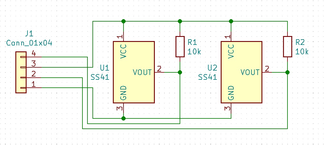
Connections can be seen in the following diagram. 10k pull-up resistors are mostly for testing purposes (tuning position of sensors) but can stay in place in the final circuit also.
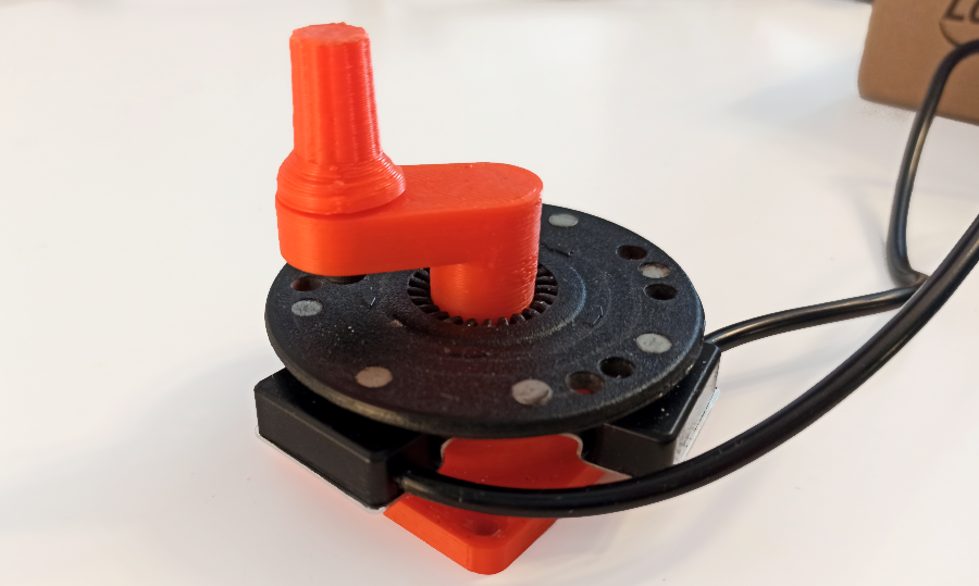
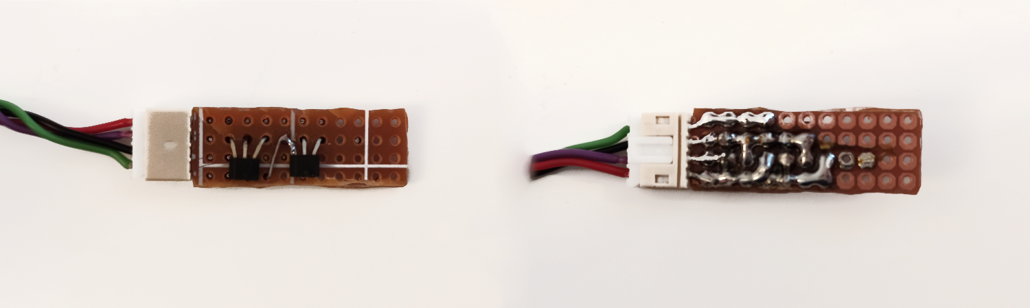
In practice, I used a universal board to make a circuit.
Software support
Fortunately, support for the encoder is embedded in STM32F4 timers and even more support is given by the VESC system itself, so setting up this whole thing takes only a minute. I connected “encoder” outputs to STM32 to pins B6 and B7, external pullup is already on board so there is no need for setting up internal pullups.
My implementation of can be found in file app_pas_encoder.c
Initialization takes only a couple of lines:
#define ENCODER_RELOAD_VALUE        1000

void app_pas_encoder_init(void)
{
...
    encoder_init_abi(ENCODER_RELOAD_VALUE);
...
}
After that value interesting for us can be read from the timer CNT register
uint32_t encoder_position = HW_ENC_TIM->CNT;
Main cyclist pedal movement is determined in function calculate_action_from_position. That function is called every 10ms from the task and contains a state machine to preserve the previous state. It also makes some simple averaging and sends the signal to listeners (by use of events) about full turn back detection (further it will be used for arming and disarming the controller). I think there is no point to write more about it, small diagram and code in c should explain everything clearly.
static void calculate_action_from_position(uint32_t encoder_position){
    static uint32_t previous_encoder_position = 0U;
    static mov_type_enum previous_state = MOV_TYPE_NO_MOVE_OR_TOO_SLOW;
    static uint32_t backward_turn_detection_start_position = 0U;
    static bool turn_back_detected = false;

    position_delta = (float) calculate_encoder_delta(previous_encoder_position, encoder_position);
    angle_delta = ((float)position_delta/(float)FULL_CIRCLE_ENCODER_STEPS)*360.0f;
    speed = (angle_delta * 1000.0f)/ (float)THREAD_SLEEP_TIME;

    speed_running_avg = (speed_running_avg * (float)(SPEED_AVG_CONSTANT-1) + speed)/(float)SPEED_AVG_CONSTANT;

    switch(state)
    {
        case MOV_TYPE_NO_MOVE_OR_TOO_SLOW:
            if(speed_running_avg > MOV_FORWARD_SPEED_THR){
                state = MOV_TYPE_MOV_FORWARD;
            }
            else if(speed_running_avg < MOV_BACKWARD_SPEED_THR){
                state = MOV_TYPE_MOV_BACKWARD;
            }
            else{
                /*do nothing */
            }
            break;
        case MOV_TYPE_MOV_FORWARD:
            if(speed_running_avg < (MOV_FORWARD_SPEED_THR - MOV_SPEED_HYSTERESIS))
            {
                state = MOV_TYPE_NO_MOVE_OR_TOO_SLOW;
            }
            break;
        case MOV_TYPE_MOV_BACKWARD:
            if(speed_running_avg > (MOV_BACKWARD_SPEED_THR + MOV_SPEED_HYSTERESIS))
            {
                state = MOV_TYPE_NO_MOVE_OR_TOO_SLOW;
            }
            break;
        default:
            commands_printf("Something goes wrong");
            break;
    }

    if(state != previous_state)
    {
        commands_printf("State transition %s -> %s",
            mov_state_type_to_string(previous_state), mov_state_type_to_string(state));
    }

    if(state == MOV_TYPE_MOV_BACKWARD)
    {
        if(previous_state != MOV_TYPE_MOV_BACKWARD)
        {
            backward_turn_detection_start_position = encoder_position;
        }

        if(turn_back_detected == false){
            if(calculate_encoder_delta(backward_turn_detection_start_position, encoder_position) < BACKWARD_MOVEMENT_TURN_THR)
            {
                send_event_about_turn_back();
                commands_printf("Turn back detected");
                turn_back_detected = true;
            }
        }
    }
    else
    {
        turn_back_detected = false;
    }

    previous_encoder_position = encoder_position;
    previous_state = state;
}
PAS in action
#TODOPICTURE PICTURE OF ORIGINAL ON A BIKE